Electronics is a physical pursuit in the sense that you have to build circuits to test and use them. However there is a lot to be said for using simulation to try things out. Its much easier and you can check that you have correctly designed a circuit before going to the trouble of building it. The good news is that circuit simulation is a lot easier than you might imagine using open source software.
This is a chapter from our ebook on electronics as applied to the art of digital design or the IoT.
The full contents can be seen below. Notice this is a first draft and a work in progress.
Chapter List
-
Resistance Is (Not) Futile
Electronics is a complicated subject with lots of different types of electronic components. Electronics as it is applied to the IoT or digital electronics in general is in fact a much simpler subject. In particular you can master it with a knowledge of just a small number of devices - the resistor being the number one. In this chapter we look at the basic ways that electricity behaves and how resistors control it.
-
Meet The Sims - Simulating Circuits
Electronics is a physical pursuit in the sense that you have to build circuits to test and use them. However there is a lot to be said for using simulation to try things out. Its much easier and you can check that you have correctly designed a circuit before going to the trouble of building it. The good news is that circuit simulation is a lot easier than you might imagine using open source software.
-
Lowering The Voltage Coming Soon
-
The Transistor BJT
-
The FET
-
Your Workshop - Basic Tools
-
Driving Simple Loads
-
Motors
-
Inputs
-
DAC
-
ADC
-
Logic
If you are new to electronics I encourage you to try using a simulator. At first it will help you understand what you are doing much better than actually building a circuit. You can modify things very easily and make lots of measurements in a single click - measurements that would take too long any other way. You can see the effects of your changes and learn so much more so much more quickly. Even when you move from the beginner stage you will still find that a simulator lets you test your circuits before you invest time in building them.
There are so many advantages to learning to use a simulator that it is surprising that it isn't the standard way to learn electronics.
In the rest of the book a simulator will be used to explain and explore the circuits and behaviors that are under discussion so you do need a simulator and know how to use it.
The good news is that it isn't difficult and it doesn't cost anything.
The only big problem is selecting which simulation package to use. There are some well known commercial packages and if you are serious about electronic design then investing in one of these is a good idea. There are also free but not open source, my own favorite is LTSpice from Linear Technology. However these free simulators have their own problems in being linked to the commercial interests of companies selling you particular components.
Installing Qucs
My own preferred open source solution is Qucs - it works well and has lots of models, simulations and it can be extended easily. Its biggest problem is that it lacks documentation and its not often intuitive. Its name stands fro Quite Universal Circuit Simulator which confirms the observation that open source project aren't very good at finding names for their creations.
Qucs isn't the most polished simulator from the point of view of the UI but it is very capable and once you get used to its peculiarities you start to ignore them.
Your first task is to download a binary for the OS you want to work with from the Qucs website.
http://qucs.sourceforge.net/
There is a binary for Windows, OSX and Ubuntu (and other Linux OS). All you have to do is do expand the compressed file into a suitable directory - which directory doesn't matter. Then find gucs.exe in the bin directory and create a shortcut on the desktop or where ever you find convenient.
When you start the program you will see a blank design area and a palette on the left hand side.
The first thing to do is select the components tab to see a selection of common components:
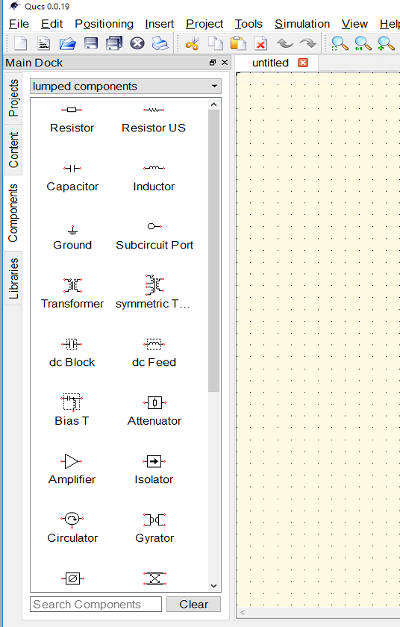
You can select one of the components, a resistor say and each time you click on the design surface you can drop another resistor symbol. This way you can build up the components you need.
The components are autonumbered, in the case of resistors R1, R2 and so on and have default properties - 50Ohms for resistors.
You can change the properties by selecting the point tool and then right clicking on the symbol and select Edit Properties
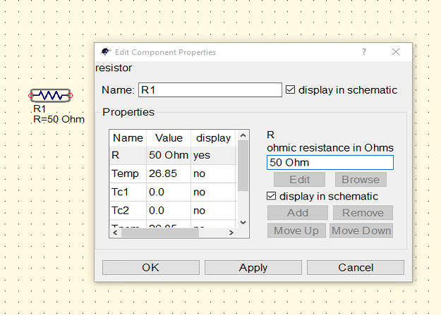
In the case of most components you will only change the major property i.e. the resistance of a resistor and trust that everything else is set appropriately.
The symbol you have placed on the surface might not be in the correct orientation. You can rotate or mirror it by selecting the arrow tool, clicking on the component and then selecting one of the mirror or rotation tools.:
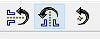
You can also right click while you are placing the component into the diagram to rotate it.
These tools are easy to understand but there is one small trick you need to know if you are to avoid a lot of frustration. When you first place a component on the surface it is grid aligned which makes it possible to wire up the circuit. If you rotate or mirror a component its wire ends might become un-aligned with the grid and this makes it impossible to wire them up. To align them to the grid use the Positioning, Set on Grid command - short cut Ctrl-U.
The final tool you need to know about is the wiring tool which you can use to connect components together. This is tricky at first but eventually you get used to it. Click on wire endpoints and move horizontally and vertically to route a wire to the next end point where the wire is terminated automatically when you click a second time. You can change the direction of the wire either by clicking on the surface to anchor it or by right clicking.
The best way to learn it to simply try out what happens.
Notice that the circuit that you create is naturally a schematic diagram rather than a picture of real components wired together. This is yet another good reason to learn to use and read schematics.
Now it is time to create the first circuit we looked at in chapter 1.
- Prev
- Next >>