The Fastest Pulse
First we need to set it to output and GPIO 4 is controlled by FSEL0 and bits 12,13 and 14 which we want to set to 001 i.e. we need to store 0x1000 in FSEL0:
*paddr=0x1000;
With GPIO 4 set to output we now need to use the SET0 and CLR0 registers to set the line high and low. As we want to do this as fast as possible we need to precompute the addresses of SET0 and CLR0:
volatile uint32_t* paddr1 = map + 0x1C/4;
volatile uint32_t* paddr2 = map + 0x28/4;
for(;;){
*paddr1=0x10;
*paddr2=0x10;
};
The complete program is:
#include <stdio.h>
#include <stdlib.h>
#include <bcm2835.h>
#include <sys/mman.h>
#include <fcntl.h>
#include <errno.h>

int main(int argc, char** argv) {
int memfd = open("/dev/mem", O_RDWR | O_SYNC);
uint32_t * map = (uint32_t *)mmap(
                    NULL,
                    4*1024,
                    (PROT_READ | PROT_WRITE),
                    MAP_SHARED,
                    memfd,
                    0x3f200000);
 if (map == MAP_FAILED)
    printf("bcm2835_init: %s mmap failed: %s\n", strerror(errno));
close(memfd);

volatile uint32_t* paddr = map;
*paddr=0x1000;
volatile uint32_t* paddr1 = map + 0x1C/4;
volatile uint32_t* paddr2 = map + 0x28/4;
for(;;){
 *paddr1=0x10;
 *paddr2=0x10;
};
    return (EXIT_SUCCESS);
}
If you run this program you will discover that it generates pulses that are as small as 0.25 microseconds (Pi 2 and Zero). This is as fast as you can go using memory mapped file access.
Because of all of the complexities and differences between the Pi 1 and P2 you are much better off using the bcm2835 library which uses exactly these technique to work with the GPIO and isn't much slower than a custom code approach.
Lets look at the lower lever functions that the library provides.
Low Level Register Access
The bcm2835 library provides a small number of functions that will access any register you need to. It makes use of the /dev/mem file and the mmap function and it works in more or less the way described above. The big advantage is that it sets things up so that the addressing is correct for the current and presumably future versions of the Pi.
There are two read and two write functions:
uint32_t bcm2835_peri_read (volatile uint32_t *paddr)
uint32_t bcm2835_peri_read_nb (volatile uint32_t *paddr)

void bcm2835_peri_write (volatile uint32_t *paddr, uint32_t value)
void bcm2835_peri_write_nb (volatile uint32_t *paddr, uint32_t value)
The difference between them is the use of read/write barriers. This is something that has been ignored until now. The processor allows operations to occur in an almost synchronous way. This means that it is possible for results to occur out of order to the way you programmed them. This can only happen on the first access to a peripheral. If you read or write to a peripheral for the first time you need to use a barrier. Subsequent reads and writes don't need a barrier. If you write to another peripheral and then go back to the first you need to use a barrier again. In short you need a barrier at the start of any consecutive peripheral accesses.
It is always safer to use standard read/write functions that apply a barrier than the nb - non-barrier functions - however these are slightly faster.
As well as the four basic read/write functions we also have a set function:
void bcm2835_peri_set_bits (volatile uint32_t *paddr, uint32_t value, uint32_t mask)
This will set the bits defined in the mask to the value specified in the corresponding bit in the value parameter. For example
bcm2835_peri_set_bits (paddr,0x01,0x01)
will set bit 0 to a 1 leaving all other bits unchanged and
bcm2835_peri_set_bits (paddr,0x00,0x01)
will set bit 0 to a 0 leaving all other bits unchanged.
Finally we have the problem of specifying the addresses we want to use. The problem is of course what is the base address?
There is a useful function that will return the base address of any of the standard registers:
uint32_t * bcm2835_regbase (uint8_t regbase)
and regbase is one of
So to get the address in user memory of the GPIO register you can use BCM2835_REGBASE_GPIO.
Alternatively you can use bcm2835_peripherals and simply add the known offsets e.g.
bcm2835_peripherals + BCM2835_REGBASE_GPIO/4;
The library also provides a set of precomputed starting addresses for the standard sets of registers:
bcm2835_gpio = bcm2835_peripherals + BCM2835_GPIO_BASE/4;
bcm2835_pwm  = bcm2835_peripherals + BCM2835_GPIO_PWM/4;
bcm2835_clk  = bcm2835_peripherals + BCM2835_CLOCK_BASE/4;
bcm2835_pads = bcm2835_peripherals + BCM2835_GPIO_PADS/4;
bcm2835_spi0 = bcm2835_peripherals + BCM2835_SPI0_BASE/4;
bcm2835_bsc0 = bcm2835_peripherals + BCM2835_BSC0_BASE/4; /* I2C */
bcm2835_bsc1 = bcm2835_peripherals + BCM2835_BSC1_BASE/4; /* I2C */
bcm2835_st   = bcm2835_peripherals + BCM2835_ST_BASE/4;
Notice that the addresses all refer to the location in user space where the file has been mapped and all of the offsets have to be converted to word addressed by being divided by 4.
An Almost Fastest Pulse
As an example of using the low level functions let's repeat the toggling of GPIO 4 using them. This doesn't give you the fastest possible time because there is the overhead of the function calls - but it is almost as good.
This time we need to initialize the library - this is where the mapping is set up.
    if (!bcm2835_init())
        return 1;
Next we can get the address of the start of the GPIO registers in user memory:
uint32_t* gpioBASE = bcm2835_regbase(BCM2835_REGBASE_GPIO);
Finally we can set GPIO 4 to output and set and clear it:
bcm2835_peri_write(gpioBASE, 0x1000);
for (;;) {
 bcm2835_peri_write(gpioBASE + BCM2835_GPSET0 / 4, 0x10);
 bcm2835_peri_write(gpioBASE + BCM2835_GPCLR0 / 4, 0x10);
}
If you run this version of the program you will find that the smallest pulses are around 0.5 microseconds (PI 2 and Zero).
If you change the writes for non-barrier writes then the pulses do get shorter - typically 0.3 microseconds (PI 2 and Zero) but there is much more variability.
In practice using the barrier read/writes seems adequate.
GPIO Clocks - An Example
This is an advanced topic.
The GPIO Clocks are a facility isn't as well known as they deserve to be and there are no functions that let you work with them in the bcm2835 library - but it fairly easy to add one.
There are three general purpose GPIO clocks and two special purpose clocks - the PWM and PCM clock, You can set any of the clocks to run at a given rate and the general purpose clocks can be routed to a subset of GPIO pins. The outputs are pulse trains of the sepecified frequency which can be modulated by changing the clock divider.
The frequency division can include a fractional part which, if you know your digital logic, is surpising. Dividing by 2, 4 or 8 is easy but how do you divide by 2.5? The answer is that you use a MASH filter. Exactly how this works is beyond the scope of this book to explain but it is a digital processing technique that can generate a signal with the frequency desired. The problem is that it also generates additional error frequencies that with luck are outside of the band required and easy to remove. If you opt for no MASH filter then you cannot use a fractional divider. Selecting one, two or three MASH filters produces the required frequecny but with different properties of noise associated with the signal.
There are three GPIO clocks which can be used with the following GPIO lines:
GPCLK0 GPIO4 GPIO20 GPIO32 GPIO34 GPIO44
GPCLK1 GPIO5 GPIO21 GPIO42
GPCLK2 GPIO6 GPIO43
The only GPIO pin available on early Pis is GPIO4 but on B+/2 you can use the following:
GPIO4  GPCLK0 ALT0
GPIO5  GPCLK1 ALT0 (reserved for system use)
GPIO6  GPCLK2 ALT0
GPIO20 GPCLK0 ALT5
Each clock is controlled by two registers: a control register and a register used to specify the clock divider.
The word, multiply by 4 for byte address, offsets for the registers are:
#define CLK_GP0_CTL 28
#define CLK_GP0_DIV 29

#define CLK_GP1_CTL 30
#define CLK_GP1_DIV 31

#define CLK_GP2_CTL 32
#define CLK_GP2_DIV 33

#define CLK_PCM_CTL 38
#define CLK_PCM_DIV 39

#define CLK_PWM_CTL 40
#define CLK_PWM_DIV 41
The offsets are all relative to
BCM2835_CLOCK_BASE 0x101000
which is a byte address relative to the start of the perhiperhal area or to
bcm2835_clk
which is a word address relative to the start of the memory mapped registers.
The safest way to form the address of a clock register, GP0 control for example, is to use
bcm2835_clk+CLK_GP0_CTL
as the bcm2835_clk is automatically adjusted for the start ot he perhipherals as mapped in memory.
The control register has a simple layout:
31-24 PASSWD Clock Manager password “5a”

10-9 MASH MASH  control
      0 = integer division
      1 = 1-stage MASH
      2 = 2-stage MASH
      3 = 3-stage MASH
 8 FLIP Invert the clock generator output
 7 BUSY Clock generator is running
 6 - Unused
 5 KILL Kill the clock generator
      0 = no action 1 = stop
4 ENAB Enable the clock generator
3-0 SRC Clock source
      0 = GND
      1 = oscillator        19.2MHz
      2 = testdebug0
      3 = testdebug1
      4 = PLLA              0MHz
      5 = PLLC              1000MHz
      6 = PLLD              500MHz
      7 = HDMI auxiliary    216MHz
 8-15 = GND
The important points are that you use ENAB to start and stop the clock. You don't make changes to the settings while the clock is running and you don't make changes while enabling the clock.
The divider register has the format:
31-24 PASSWD Clock Manager password “5a”
23-12 DIVI Integer part of divisor
11-0 DIVF Fractional part of divisor
and as for the control register you do not change this while BUSY=1.
So to configure the clock you:
- Set ENAB low
- Wait for BUSY to go low
- Set the values you want to change including the divider register but with ENAB low
- Set ENAB high with the same set of values so as not to change them.
Now we can put this together to write a function that will set the clock assocated with GPIO 4, you can easily change this to work with any of the valid GPIO lines:
#define CLK_GP0_CTL 28
#define CLK_GP0_DIV 29
void bcm2835_GPIO4_set_clock_source(
           uint32_t source,
           uint32_t divisorI,
           uint32_t divisorF) {
 if (bcm2835_clk == MAP_FAILED)
       return;
 divisorI &= 0xfff;
 divisorF &= 0xfff;
 source &= 0xf;

 uint8_t mask=bcm2835_peri_read(bcm2835_clk + CLK_GP0_CTL)
           & 0xffffffef;

 bcm2835_peri_write(bcm2835_clk + CLK_GP0_CTL,
                     BCM2835_PWM_PASSWRD | mask);

 while ((bcm2835_peri_read(bcm2835_clk + CLK_GP0_CTL) & 0x80) != 0){};

 bcm2835_peri_write(bcm2835_clk + CLK_GP0_DIV,
  BCM2835_PWM_PASSWRD | (divisorI << 12) | divisorF);
 bcm2835_peri_write(bcm2835_clk + CLK_GP0_CTL,
  BCM2835_PWM_PASSWRD |  source|0x200);
 bcm2835_peri_write(bcm2835_clk + CLK_GP0_CTL,
  BCM2835_PWM_PASSWRD | 0x0210 | source);
}
At the start of the function we make sure that the divisors and the source are withing the legal range by anding them with masks. Next we read the control register so as to create a mask so that we don't change any of the bits until the clock is stopped. Notice that the enable bit of the mask is set to zero which is why the clock stops when the mask is written back to the control register. The while loop waits for the clock to stop and then the divsor is written to the divisor register and the source to the control register. Finally the source is written to the control register along with an enable bit set to 1. The 0x200 selects one stage of MASH which is necessary if you want to use the fractional divider. Also notice that we are using the predefined BCM2835_PWM_PASSWRD for 0x5A to allow a write to the registers.
You can try this out with a main program something like:
 if (!bcm2835_init())
        return 1;
    bcm2835_gpio_fsel(4, BCM2835_GPIO_FSEL_ALT0);
    bcm2835_GPIO4_set_clock_source(6, 50, 0);
If you look at the output of GPIO 4 with a logic analyzer you might be surprised how jittery the 10MHz i.e. 500MHz/50 clock is. Part of this is likely to be due to the poor wave shape at such a high frequecny. If you look at the pulse stream on an oscilloscope then you should see something like:
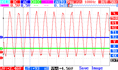
The maximum frequency that can be produced depends on the loading on the GPIO pin and stray capacitance. In theory you should be able to get up to over 100MHz in practice this is difficult. As the frequency goes up the losses due to capacitance increase and the output voltage falls. Add to this the fact that many oscilloscopes will not record a signal at 100MHz and it gets very difficult to work with dividers smaller than 20 because you can't see the output.
With a divider of 5 you can still get enough of a signal to use the output as a 100MHz FM transmitter. There are programs that make use of this effect to send an FM audio signal at by changing the frequency via the fractional divider.
Conclusion
Learning how to access the GPIO registers using memory mapping isn't so much important for using the GPIOs as extending what can be done to the other registers. Once you understand the Linux performs memory mapping you can see that it is a much more general mechanism that can be applied in other situations. However most of the time you can start out using the library and only think about doing anything more complicated if it proves necessary. Before implementing your own memory mapping make sure you try the low level register functions - they are almost as fast as anything you can create.
Now On Sale!
You can now buy a print or ebook edition of Raspberry Pi IoT in C from Amazon.
For Errata and Listings Visit: IO Press
This our ebook on using the Raspberry Pi to implement IoT devices using the C programming language. The full contents can be seen below. Notice this is a first draft and a work in progress.
Chapter List
-
Introducing Pi (paper book only)
-
Getting Started With NetBeans In this chapter we look at why C is a good language to work in when you are creating programs for the IoT and how to get started using NetBeans. Of course this is where Hello C World makes an appearance.
-
First Steps With The GPIO
The bcm2835C library is the easiest way to get in touch with the Pi's GPIO lines. In this chapter we take a look at the basic operations involved in using the GPIO lines with an emphasis on output. How fast can you change a GPIO line, how do you generate pulses of a given duration and how can you change multiple lines in sync with each other? -
GPIO The SYSFS Way
There is a Linux-based approach to working with GPIO lines and serial buses that is worth knowing about because it provides an alternative to using the bcm2835 library. Sometimes you need this because you are working in a language for which direct access to memory isn't available. It is also the only way to make interrupts available in a C program. -
Input and Interrupts
There is no doubt that input is more difficult than output. When you need to drive a line high or low you are in command of when it happens but input is in the hands of the outside world. If your program isn't ready to read the input or if it reads it at the wrong time then things just don't work. What is worse is that you have no idea what your program was doing relative to the event you are trying to capture - welcome to the world of input. -
Memory Mapped I/O
The bcm2835 library uses direct memory access to the GPIO and other peripherals. In this chapter we look at how this works. You don't need to know this but if you need to modify the library or access features that the library doesn't expose this is the way to go. -
Near Realtime Linux
You can write real time programs using standard Linux as long as you know how to control scheduling. In fact it turns out to be relatively easy and it enables the Raspberry Pi to do things you might not think it capable of. There are also some surprising differences between the one and quad core Pis that make you think again about real time Linux programming. -
PWM
One way around the problem of getting a fast response from a microcontroller is to move the problem away from the processor. In the case of the Pi's processor there are some builtin devices that can use GPIO lines to implement protocols without the CPU being involved. In this chapter we take a close look at pulse width modulation PWM including, sound, driving LEDs and servos. -
I2C Temperature Measurement
The I2C bus is one of the most useful ways of connecting moderately sophisticated sensors and peripherals to the any processor. The only problem is that it can seem like a nightmare confusion of hardware, low level interaction and high level software. There are few general introductions to the subject because at first sight every I2C device is different, but here we present one. -
A Custom Protocol - The DHT11/22
In this chapter we make use of all of the ideas introduced in earlier chapters to create a raw interface with the low cost DHT11/22 temperature and humidity sensor. It is an exercise in implementing a custom protocol directly in C. -
One Wire Bus Basics
The Raspberry Pi is fast enough to be used to directly interface to 1-Wire bus without the need for drivers. The advantages of programming our own 1-wire bus protocol is that it doesn't depend on the uncertainties of a Linux driver. -
iButtons
If you haven't discovered iButtons then you are going to find of lots of uses for them. At its simples an iButton is an electronic key providing a unique coce stored in its ROM which can be used to unlock or simply record the presence of a particular button. What is good news is that they are easy to interface to a Pi. -
The DS18B20
Using the software developed in previous chapters we show how to connect and use the very popular DS18B20 temperature sensor without the need for external drivers. -
The Multidrop 1-wire bus
Some times it it just easier from the point of view of hardware to connect a set of 1-wire devices to the same GPIO line but this makes the software more complex. Find out how to discover what devices are present on a multi-drop bus and how to select the one you want to work with. -
SPI Bus
The SPI bus can be something of a problem because it doesn't have a well defined standard that every device conforms to. Even so if you only want to work with one specific device it is usually easy to find a configuration that works - as long as you understand what the possibilities are. -
SPI MCP3008/4 AtoD (paper book only)
-
Serial (paper book only)
-
Getting On The Web - After All It Is The IoT (paper book only)
-
WiFi (paper book only)
- << Prev
- Next