
If you haven't discovered iButtons then you are going to find of lots of uses for them. At its simples an iButton is an electronic key providing a unique code stored in its ROM which can be used to unlock or simply record the presence of a particular button. What is good news is that they are easy to interface to a Pi.
Now On Sale!
You can now buy a print or ebook edition of Raspberry Pi IoT in C from Amazon.
For Errata and Listings Visit: IO Press
This our ebook on using the Raspberry Pi to implement IoT devices using the C programming language. The full contents can be seen below. Notice this is a first draft and a work in progress.
Chapter List
-
Introducing Pi (paper book only)
-
Getting Started With NetBeans In this chapter we look at why C is a good language to work in when you are creating programs for the IoT and how to get started using NetBeans. Of course this is where Hello C World makes an appearance.
-
First Steps With The GPIO
The bcm2835C library is the easiest way to get in touch with the Pi's GPIO lines. In this chapter we take a look at the basic operations involved in using the GPIO lines with an emphasis on output. How fast can you change a GPIO line, how do you generate pulses of a given duration and how can you change multiple lines in sync with each other? -
GPIO The SYSFS Way
There is a Linux-based approach to working with GPIO lines and serial buses that is worth knowing about because it provides an alternative to using the bcm2835 library. Sometimes you need this because you are working in a language for which direct access to memory isn't available. It is also the only way to make interrupts available in a C program. -
Input and Interrupts
There is no doubt that input is more difficult than output. When you need to drive a line high or low you are in command of when it happens but input is in the hands of the outside world. If your program isn't ready to read the input or if it reads it at the wrong time then things just don't work. What is worse is that you have no idea what your program was doing relative to the event you are trying to capture - welcome to the world of input. -
Memory Mapped I/O
The bcm2835 library uses direct memory access to the GPIO and other peripherals. In this chapter we look at how this works. You don't need to know this but if you need to modify the library or access features that the library doesn't expose this is the way to go. -
Near Realtime Linux
You can write real time programs using standard Linux as long as you know how to control scheduling. In fact it turns out to be relatively easy and it enables the Raspberry Pi to do things you might not think it capable of. There are also some surprising differences between the one and quad core Pis that make you think again about real time Linux programming. -
PWM
One way around the problem of getting a fast response from a microcontroller is to move the problem away from the processor. In the case of the Pi's processor there are some builtin devices that can use GPIO lines to implement protocols without the CPU being involved. In this chapter we take a close look at pulse width modulation PWM including, sound, driving LEDs and servos. -
I2C Temperature Measurement
The I2C bus is one of the most useful ways of connecting moderately sophisticated sensors and peripherals to the any processor. The only problem is that it can seem like a nightmare confusion of hardware, low level interaction and high level software. There are few general introductions to the subject because at first sight every I2C device is different, but here we present one. -
A Custom Protocol - The DHT11/22
In this chapter we make use of all of the ideas introduced in earlier chapters to create a raw interface with the low cost DHT11/22 temperature and humidity sensor. It is an exercise in implementing a custom protocol directly in C. -
One Wire Bus Basics
The Raspberry Pi is fast enough to be used to directly interface to 1-Wire bus without the need for drivers. The advantages of programming our own 1-wire bus protocol is that it doesn't depend on the uncertainties of a Linux driver. -
iButtons
If you haven't discovered iButtons then you are going to find of lots of uses for them. At its simples an iButton is an electronic key providing a unique coce stored in its ROM which can be used to unlock or simply record the presence of a particular button. What is good news is that they are easy to interface to a Pi. -
The DS18B20
Using the software developed in previous chapters we show how to connect and use the very popular DS18B20 temperature sensor without the need for external drivers. -
The Multidrop 1-wire bus
Some times it it just easier from the point of view of hardware to connect a set of 1-wire devices to the same GPIO line but this makes the software more complex. Find out how to discover what devices are present on a multi-drop bus and how to select the one you want to work with. -
SPI Bus
The SPI bus can be something of a problem because it doesn't have a well defined standard that every device conforms to. Even so if you only want to work with one specific device it is usually easy to find a configuration that works - as long as you understand what the possibilities are. -
SPI MCP3008/4 AtoD (paper book only)
-
Serial (paper book only)
-
Getting On The Web - After All It Is The IoT (paper book only)
-
WiFi (paper book only)
A basic iButton is small can that can be placed into a simple contact reader.

Often the button is placed in a fob that makes it possible to keep on a key ring:

A typical reader is just a two contact receptacle:

iButtons are cheap and robust and they are easy to use - as long as you have some 1-wire software.
You can get very simple iButtons that store a unique serial number for a few dollars. These are suitable for security applications. You could design a reader to open a door, arm an alarm or record comings and goings. The main advantage of iButtons over swipe cards and similar id devices is that they are almost indestructible. The small stainless steel can is tough and water proof.
There are also most sophisticated iButtons that come with sensors and data loggers. These are slightly more expensive and slightly more difficult to read but after you have seen how to work with the basic security button there should be no problem in extending the software.
The Hardware
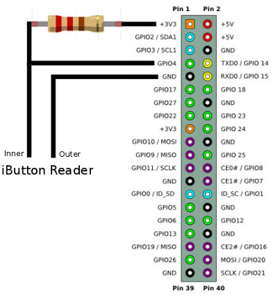
A typical iButton is used in parasitic mode meaning it derives its operating power from the data line. A typical iButton has such a low current drain that you don't need to do anything to make it work property.
All that is needed is a pullup resistor, typically 2.2KOhms, a 3.3V supply, ground and a GPIO line pin 7 in this example but it could be any other you care to use.
The circuit is almost trivial - no it really couldn't be simpler:

You can realize this an many ways. A prototype board allows you to check that things are working with a logic analyzer but you can wire it directly to the Pi's connector.
Is There a Button?
The first thing you want to try with any 1-wire device is to discover if the bus is working and to do this you send an initialization pulse. We created a function to do just this in the previous chapter so we can just use it.
However iButtons have a particular problem. You want to detect when an iButton is pressed into the reader so you need a loop something like:
  uint8_t b = 1;
  for (;;) {
    b = presence(RPI_GPIO_P1_07);
    if (b == 0) {
      read iButton
    }
   }
Where presence is a function from the previous chapter.
In practice there is also the problem that the iButton is likely to make intermittent contact and so you have to implement error checking and some way of "debouncing" the iButton so you only read it once.
For the moment we can ignore this problem and just read the iButton.
Read The Serial Number
The DS1990R and similar are very simple 1-wire devices and they only support a few commands and if it is the only device on the bus then only one of these is useful. After the initilization pulse and the device has sent its presence pulse back it waits for a command byte to be transmitted from the master.
In most cases the only command you need to send is Read ROM which is either 0x33 or 0x0F. In respond the slave then sends the unique serial number stored in its memory.
Normally you would have to send the Skip ROM command or Match ROM command to select the slave device but in this case it isn't necessary because the iButton is usually the only device on the bus.
To send the Read Rom command you use the writeByte function introduced in the previous chapter:
writeByte(RPI_GPIO_P1_07, 0x33);
Now you can read the data that the slave is read to send. The slave sends eight bytes. The first byte is the family code which identifies the type of device for a simple iButton this is a 0x01. Next it sends the six bytes of the serial number and finally a CRC check byte. Often you can ignore the check byte because the transmission is reliable and getting it wrong isn't important. In this case you can't because the connection with the iButton is subject to a lot of noise.
Reading the eight bytes is easy:
  uint8_t code[8];
  int i;
  for (i = 0; i < 8; i++) {
    code[i] = readByte(RPI_GPIO_P1_07);
  }
Now we have all of the data we need but it does need to be checked for transmission errors.
Computing The CRC
A CRC Cyclic Redundancy Checksum is often regarded as a tough problem. However once you know the basic idea you should be able implement any CRC calculation - perhaps not in the most efficient way but it will work. For low data rate applications high efficiency isn't needed and you can make use of a direct implementation.
The data sheet specified the CRC used as a shift register:
The first thing to notice is the polynomial that defines the CRC. This is generator polynomial and in this case it is:
X8 + X5 + X4 + 1.
The first question to answer is what is the connection between binary values and polynomials?
The answer is that you can treat a binary number as the coefficients of a polynomial. For example 101 is
1*X2+0*X+1
Each bit position corresponds to a power of X. Using this notation creates a very simple relationship between multiplying by X and a left shift. For example
1*X2+0*X+1 * X = 1*X3+0*X2+1X+0
which corresponds to 101 <<1 == 1010.
You can see that this extends to multiplying one polynomial by another and even polynomial division - all accomplished by shifting and exclusive or.
The CRC is the remainder when you divide the polynomial that represents the data by the generator polynomial. The computation of the remainder is what the shift register specified on the data sheet does. The fact that the division can be implemented so simply in hardware is what makes this sort of CRC computation so common. All the hardware has to do is zero the shift register and feed the data into it. When all the data has been shifted in what is left in the shift register is the CRC i.e. the remainder.
To check the data you have received all you have to do is run it thought the shift register again and compare the computed CRC with the one received. A better trick is to also run the received CRC though the shift register when if there have been no errors will result in zero.
You can look into the theory of CRCs, bit sequences and polynomials further - and it is interesting and practically useful - but we now know everything we need to if we want to implement the CRC used by the iButton. You can delve further but all we have to do is implement the shift register in software.
From the diagram what we have to do is take each bit of the input data and exclusive or it with the least significant bit of the current shift register. If the input bit is zero then the exclusive ors in the shift register don't have any effect and the crc just has to be moved one bit to the right. If the input bit is 1 then you have to exclusive or bits at positions 3 and 4 with 1 and we have to put a 1 in at position 7 to simulate shifting a 1 into the register. i.e. exclusive or the shift register with 10001100 i.e.
So the algorithm for a single byte is:
    for (j = 0; j < 8; j++) {
            temp = (crc ^ databyte) & 0x01;
            crc >>= 1;
            if (temp)
                crc ^= 0x8C;
            databyte>>= 1;
        }
    }
First we exclusive or the data with the current CRC and extract the low order bit into temp. Then we right shift the CRC by 1 place. If the low order result, stored in temp was a 1 you have to exclusive or the CRC with 0x8C to simulate the exclusive ors in the shift register and shift in a 1 at the most significant bit. Then shift the data one place right and repeat for the next data bit.
With this worked out we can now write a function that computes the CRC for the entire 8 byte data:
uint8_t crc8(uint8_t *data, uint8_t len) {
    uint8_t i;
    uint8_t j;
    uint8_t temp;
    uint8_t databyte;

    uint8_t crc = 0;
    for (i = 0; i < len; i++) {
        databyte = data[i];
        for (j = 0; j < 8; j++) {
            temp = (crc ^ databyte) & 0x01;
            crc >>= 1;
            if (temp)
                crc ^= 0x8C;
            databyte >>= 1;
        }
    }
    return crc;
}
With this in place we can now check the CRC and print the results:
           uint8_t crc = crc8(code, 8);
            printf("CRC %hhX  ", crc);
            for (i = 0; i < 8; i++) {
                printf("%hhX ", code[i]);
            }
            printf("\n\r");
            fflush(stdout);
        }
        bcm2835_delayMicroseconds(100000);
A Complete iButton Function
Putting the functions together we can create a single function that returns a 0 if there is no iButton or if the CRC is incorrect and 1 if an iButton has been read and the CRC is ok.
int readiButton(uint8_t pin, uint8_t *data) {
    int b = presence(pin);
    if (b != 0) return 0;
    writeByte(pin, 0x33);

    int i;
    for (i = 0; i < 8; i++) {
        data[i] = readByte(pin);
    }
    uint8_t crc = crc8(data, 8);
    if (crc == 0) return 1;
    return 0;
}
Notice that if it returns a 1 then the serial number is in the second parameter which has to be passed an 8 byte array.
For example:
  int i;
    uint8_t code[8];
    for (;;) {

        int p = readiButton(RPI_GPIO_P1_07, code);
        if (p == 1) {
            for (i = 0; i < 8; i++) {
                printf("%hhX ", code[i]);
            }
            printf("\n\r");
            fflush(stdout);
        }
        bcm2835_delayMicroseconds(100000);
    };
Listing
The complete program is:
#include <bcm2835.h>
#include <stdio.h>
#include <sched.h>
#include <sys/mman.h>

int presence(uint8_t pin);
void writeByte(uint8_t pin, int byte);
uint8_t crc8(uint8_t *data, uint8_t len);
int readByte(uint8_t pin);
int readiButton(uint8_t pin, uint8_t *data);

int main(int argc, char **argv) {
    const struct sched_param priority = {1};
    sched_setscheduler(0, SCHED_FIFO, &priority);
    mlockall(MCL_CURRENT | MCL_FUTURE);

    if (!bcm2835_init())
        return 1;
    bcm2835_gpio_fsel(RPI_GPIO_P1_07, BCM2835_GPIO_FSEL_INPT);

    int i;
    uint8_t code[8];
    for (;;) {
        int p = readiButton(RPI_GPIO_P1_07, code);
        if (p == 1) {
            for (i = 0; i < 8; i++) {
                printf("%hhX ", code[i]);
            }
            printf("\n\r");
            fflush(stdout);
        }
        bcm2835_delayMicroseconds(100000);
    };
    bcm2835_close();
    return 0;
}

int presence(uint8_t pin) {
    bcm2835_gpio_fsel(pin, BCM2835_GPIO_FSEL_OUTP);
    bcm2835_gpio_write(pin, LOW);
    bcm2835_delayMicroseconds(480);
    bcm2835_gpio_fsel(pin, BCM2835_GPIO_FSEL_INPT);
    bcm2835_delayMicroseconds(70);
    uint8_t b = bcm2835_gpio_lev(pin);
    bcm2835_delayMicroseconds(410);
    return b;
}

void writeBit(uint8_t pin, int b) {

    int delay1, delay2;
    if (b == 1) {
        delay1 = 6;
        delay2 = 64;
    } else {
        delay1 = 80;
        delay2 = 10;
    }
    bcm2835_gpio_fsel(pin, BCM2835_GPIO_FSEL_OUTP);
    bcm2835_gpio_write(pin, LOW);
    bcm2835_delayMicroseconds(delay1);
    bcm2835_gpio_fsel(pin, BCM2835_GPIO_FSEL_INPT);
    bcm2835_delayMicroseconds(delay2);
}

uint8_t readBit(uint8_t pin) {
    bcm2835_gpio_fsel(pin, BCM2835_GPIO_FSEL_OUTP);
    bcm2835_gpio_write(pin, LOW);
    bcm2835_delayMicroseconds(6);
    bcm2835_gpio_fsel(pin, BCM2835_GPIO_FSEL_INPT);
    bcm2835_delayMicroseconds(9);
    uint8_t b = bcm2835_gpio_lev(pin);
    bcm2835_delayMicroseconds(55);
    return b;
}

void writeByte(uint8_t pin, int byte) {
    int i;
    for (i = 0; i < 8; i++) {
        if (byte & 1) {
            writeBit(pin, 1);
        } else {
            writeBit(pin, 0);
        }
        byte = byte >> 1;
    }
}

int readByte(uint8_t pin) {
    int byte = 0;
    int i;
    for (i = 0; i < 8; i++) {
        byte = byte | readBit(pin) << i;
    };
    return byte;
}

uint8_t crc8(uint8_t *data, uint8_t len) {

    uint8_t i;
    uint8_t j;
    uint8_t temp;
    uint8_t databyte;
    uint8_t crc = 0;
    for (i = 0; i < len; i++) {
        databyte = data[i];
        for (j = 0; j < 8; j++) {
            temp = (crc ^ databyte) & 0x01;
            crc >>= 1;
            if (temp)
                crc ^= 0x8C;

            databyte >>= 1;
        }
    }

    return crc;
}

int readiButton(uint8_t pin, uint8_t *data) {
    int b = presence(pin);
    if (b != 0) return 0;
    writeByte(pin, 0x33);
    int i;
    for (i = 0; i < 8; i++) {
        data[i] = readByte(pin);
    }
    uint8_t crc = crc8(data, 8);
    if (crc == 0) return 1;
    return 0;
}
Now On Sale!
You can now buy a print or ebook edition of Raspberry Pi IoT in C from Amazon.
For Errata and Listings Visit: IO Press
This our ebook on using the Raspberry Pi to implement IoT devices using the C programming language. The full contents can be seen below. Notice this is a first draft and a work in progress.
Chapter List
-
Introducing Pi (paper book only)
-
Getting Started With NetBeans In this chapter we look at why C is a good language to work in when you are creating programs for the IoT and how to get started using NetBeans. Of course this is where Hello C World makes an appearance.
-
First Steps With The GPIO
The bcm2835C library is the easiest way to get in touch with the Pi's GPIO lines. In this chapter we take a look at the basic operations involved in using the GPIO lines with an emphasis on output. How fast can you change a GPIO line, how do you generate pulses of a given duration and how can you change multiple lines in sync with each other? -
GPIO The SYSFS Way
There is a Linux-based approach to working with GPIO lines and serial buses that is worth knowing about because it provides an alternative to using the bcm2835 library. Sometimes you need this because you are working in a language for which direct access to memory isn't available. It is also the only way to make interrupts available in a C program. -
Input and Interrupts
There is no doubt that input is more difficult than output. When you need to drive a line high or low you are in command of when it happens but input is in the hands of the outside world. If your program isn't ready to read the input or if it reads it at the wrong time then things just don't work. What is worse is that you have no idea what your program was doing relative to the event you are trying to capture - welcome to the world of input. -
Memory Mapped I/O
The bcm2835 library uses direct memory access to the GPIO and other peripherals. In this chapter we look at how this works. You don't need to know this but if you need to modify the library or access features that the library doesn't expose this is the way to go. -
Near Realtime Linux
You can write real time programs using standard Linux as long as you know how to control scheduling. In fact it turns out to be relatively easy and it enables the Raspberry Pi to do things you might not think it capable of. There are also some surprising differences between the one and quad core Pis that make you think again about real time Linux programming. -
PWM
One way around the problem of getting a fast response from a microcontroller is to move the problem away from the processor. In the case of the Pi's processor there are some builtin devices that can use GPIO lines to implement protocols without the CPU being involved. In this chapter we take a close look at pulse width modulation PWM including, sound, driving LEDs and servos. -
I2C Temperature Measurement
The I2C bus is one of the most useful ways of connecting moderately sophisticated sensors and peripherals to the any processor. The only problem is that it can seem like a nightmare confusion of hardware, low level interaction and high level software. There are few general introductions to the subject because at first sight every I2C device is different, but here we present one. -
A Custom Protocol - The DHT11/22
In this chapter we make use of all of the ideas introduced in earlier chapters to create a raw interface with the low cost DHT11/22 temperature and humidity sensor. It is an exercise in implementing a custom protocol directly in C. -
One Wire Bus Basics
The Raspberry Pi is fast enough to be used to directly interface to 1-Wire bus without the need for drivers. The advantages of programming our own 1-wire bus protocol is that it doesn't depend on the uncertainties of a Linux driver. -
iButtons
If you haven't discovered iButtons then you are going to find of lots of uses for them. At its simples an iButton is an electronic key providing a unique coce stored in its ROM which can be used to unlock or simply record the presence of a particular button. What is good news is that they are easy to interface to a Pi. -
The DS18B20
Using the software developed in previous chapters we show how to connect and use the very popular DS18B20 temperature sensor without the need for external drivers. -
The Multidrop 1-wire bus
Some times it it just easier from the point of view of hardware to connect a set of 1-wire devices to the same GPIO line but this makes the software more complex. Find out how to discover what devices are present on a multi-drop bus and how to select the one you want to work with. -
SPI Bus
The SPI bus can be something of a problem because it doesn't have a well defined standard that every device conforms to. Even so if you only want to work with one specific device it is usually easy to find a configuration that works - as long as you understand what the possibilities are. -
SPI MCP3008/4 AtoD (paper book only)
-
Serial (paper book only)
-
Getting On The Web - After All It Is The IoT (paper book only)
-
WiFi (paper book only)
Related Articles
Real Raspberry Pi - Getting Started And Custom NOOBS